First graphs for simple supported beam made of brass and the values show a liner relation between load and displacement in ½ spans. The support reactions as indicated in the free-body diagram are A y A x and M.
Solved For The Cantilever Beam And Loading Shown Determine Chegg Com
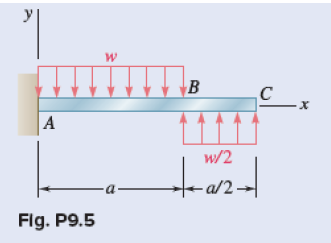
The cantilever beam shown in Fig.
. Not over the whole spanUDL. Handy calculators have been. Beam equations for Resultant Forces Shear Forces Bending Moments and Deflection can be found for each beam case shown.
A cantilever beam is subjected to a uniformly distributed load and an inclined concentrated load as shown in figure 39a. Beam Design Formulas. Capacities are determined based on a uniformly distributed load on the cantilever arms.
Find the height h if the maximum deflection is not to. When in doubt about the rigidity it is safer to assume that the beam is freely. E48 has a rectangular cross-section 50 mm wide by h mm high.
In this article Learn cantilever beam Bending moment diagram BMD. Somewhere on the beamCombination of Point Loads and UDL. However they do provide starting a place where the input file is similar to that of more familiar Finite-Element Analysis software.
The length of your rack braces refers to the distance between the On Center OC of the upright tower as shown in the diagram above. From support to some distanceUDL. In practice it is not usually possible to obtain perfect fixing and the fixing moment applied will be related to the angular movement of the support.
These scripts do not take advantage of the Tcl scripting capabilities shown in the later examples. How to determine the Cantilever Bracing Lengths. 2D Elastic Cantilever.
Simply select the picture which most resembles the beam configuration and loading condition you are interested in for a detailed summary of all the structural properties. The free-body diagram of the entire beam is shown in Figure 39b. Subsequent examples should be used as the basis for user input files.
Six different experiments were performed to study and understand the deflection of simple supported beam and cantilever beam and results are been shown in two tables and six graphs in result section. A beam which is fixed at one end in this way is called a Cantilever. Of a cantilever beam having point load at the endseveral point loadsUDL.
Determine the reactions at support A. If both ends are fixed in this way the reactions are not statically determinate. Over Whole Span UDL.
And shear force diagram SFD. Loading the arms unevenly can reduce their capacities by up to half. Now each graph will be discussed here.
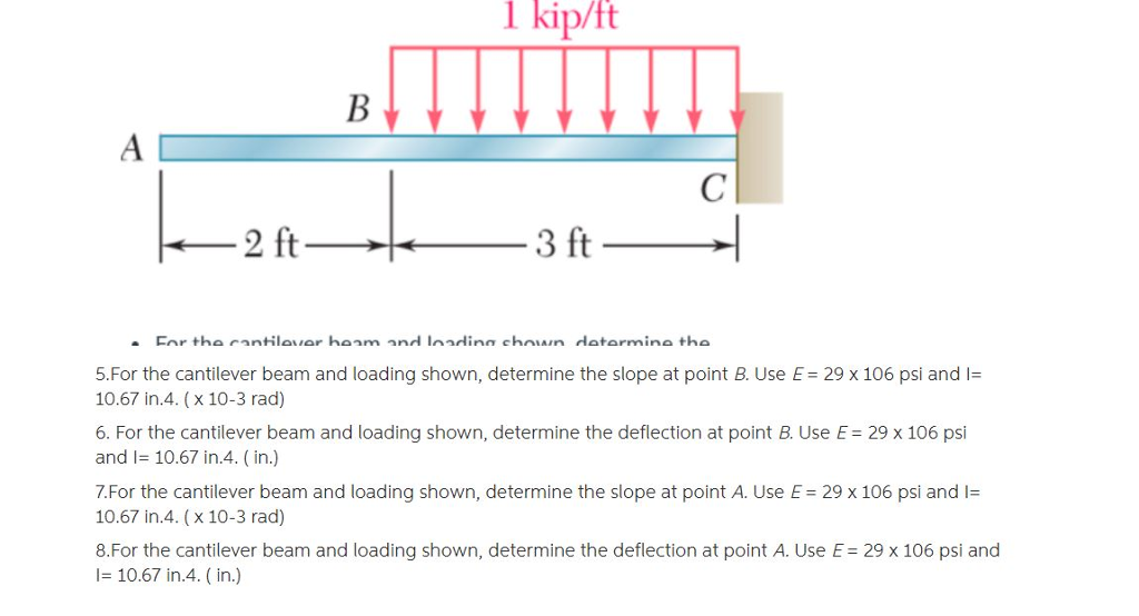
Solved 1 Kip Ft 5 For The Cantilever Beam And Loading Shown Chegg Com
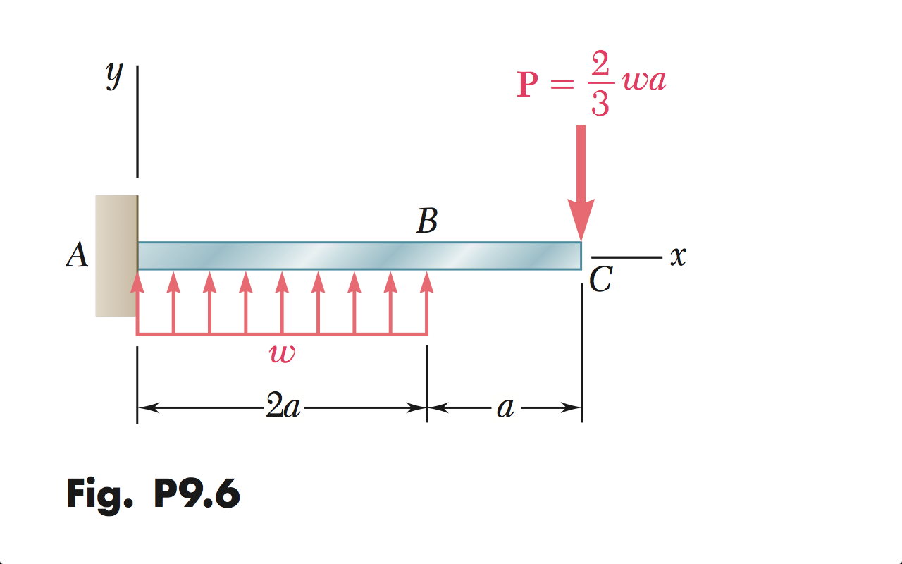
Solved Problem 9 5 For The Cantilever Beam And Loading Chegg Com

Draw The Shear Diagram For Cantilever Beam Bending Moment Beams Diagram


0 Comments